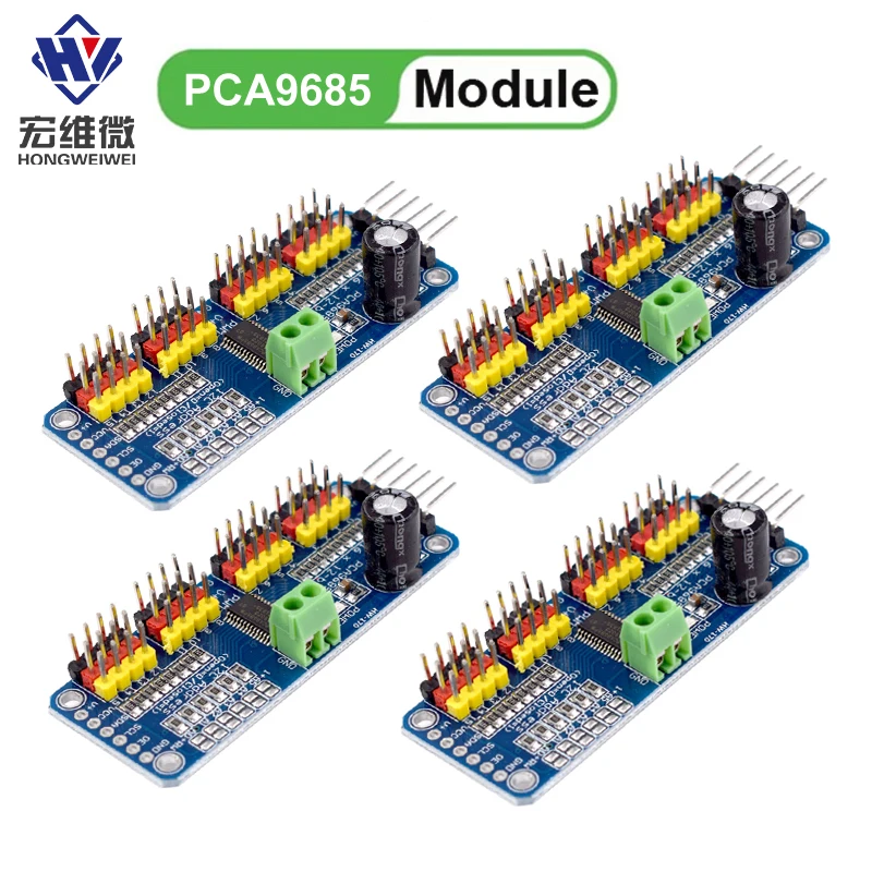
1-10PCS PCA9685 Robot Controller IIC Interface 16 Channel 12-Bit PWM Servo Motor Driver Board for Arduino Robot/ Raspberry Pi
1-10PCS PCA9685 Robot Controller IIC Interface 16 Channel 12-Bit PWM Servo Motor Driver Board for Arduino Robot/ Raspberry PiProduct Introduction:The servo driver board uses PCA9685 chip, which is a 16 channel 12 bit PWM servo driver with I2C communication. It requires two I2C lines to drive 16 channels of PWM, and the cycle and duty cycle are controllable. Not only that, it also supports cascading multiple modules. You can also change the device ID and control the switch, PWM, and duty cycle of
Need help before you buy?
Call iBuyRobotics for product guidance, compatibility questions, bulk orders, or support.
(855) I-BUY-ROBO (855) 428-97621-10PCS PCA9685 Robot Controller IIC Interface 16 Channel 12-Bit PWM Servo Motor Driver Board for Arduino Robot/ Raspberry Pi
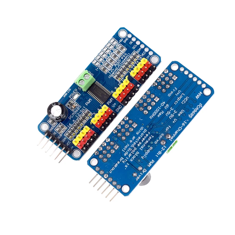
Product Introduction:
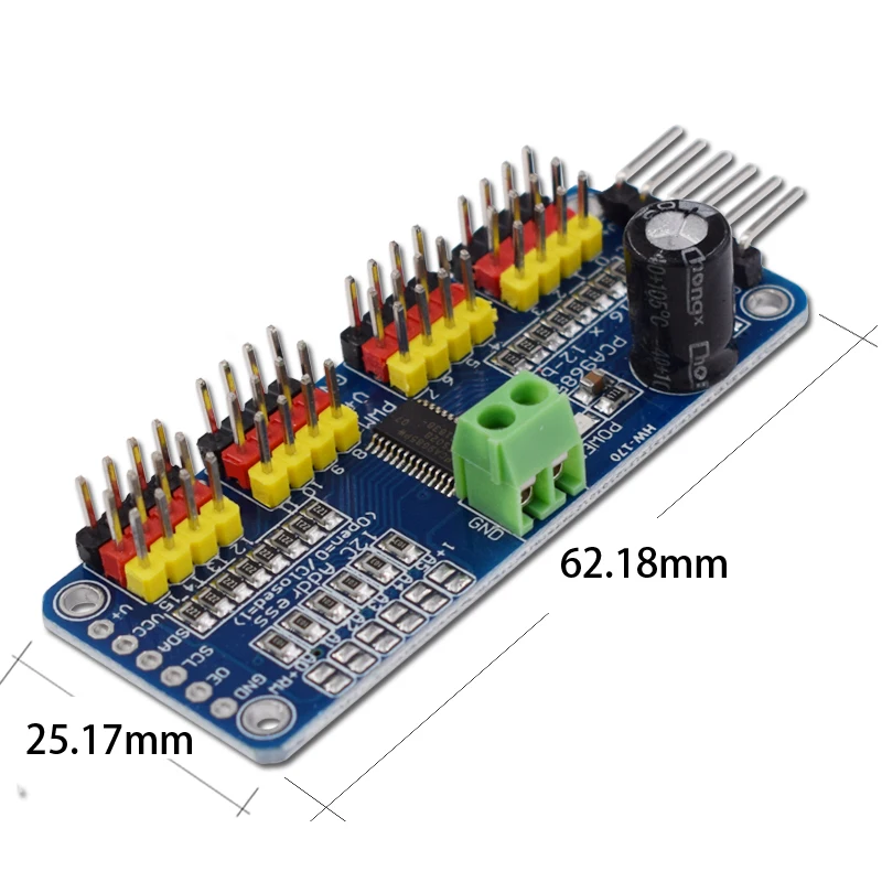
The servo driver board uses PCA9685 chip, which is a 16 channel 12 bit PWM servo driver with I2C communication. It requires two I2C lines to drive 16 channels of PWM, and the cycle and duty cycle are controllable. Not only that, it also supports cascading multiple modules. You can also change the device ID and control the switch, PWM, and duty cycle of 16 output terminals.
Features:
1. I2C communication
2. The logic power supply voltage is 3-5V, and the maximum servo power supply voltage is 6V. The logic voltage and servo voltage are supplied separately
3. Logic power indicator light
4. Introduce 16 sets of 3-pin servo motor interfaces for easy connection of 16 servo motors at once
5. Cascade design, convenient for cascading the next 16 channel servo module
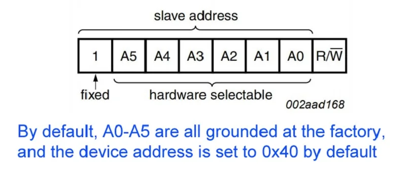
6. All PWM output lines have a 220 ohm resistor used as the address for signal output protection devicesDue to the fact that the device addresses of the chip are determined by pins A0, A1, A2, A3, A4, and A5, there can be 64 device addresses. However, since the chip retains the LED ALL Call address (1110 000) and Software Reset address (00000 110) when powered on, there are actually only 62 available device addresses. Therefore, theoretically, one I2C interface can control 992 PWM channels of 16 * 62. The schematic diagram of the pin control device address is as follows (detailed instructions need to be found in the chip data manual)
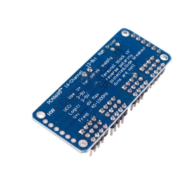
The logic power supply voltage is 3-5V, and the maximum servo power supply voltage is 6V. Separate power supply for logic voltage and servo voltageThe logic power supply voltage is 3-5V, and the maximum servo power supply voltage is 6V. Separate power supply for logic voltage and servo voltage.
This board/chip uses I2C 7-bit address between 0x60-0x80, selectable with jumpers
Terminal block for power input (or you can use the 0.1" breakouts on the side)
Reverse polarity protection on the terminal block input
Green power-good LED
3 pin connectors in groups of 4 so you can plug in 16 servos at once (Servo plugs are slightly wider than 0.1" so you can only stack 4 next to each other on 0.1" header
"Chain-able" design
A spot to place a big capacitor on the V+ line (in case you need it)
220 ohm series resistors on all the output lines to protect them, and to make driving LEDs trivial
Solder jumpers for the 6 address select pins
i2c-controlled PWM driver with a built in clock. Unlike the TLC5940 family, you do not need to continuously send it signal tying up your microcontroller, its completely free running!
It is 5V compliant, which means you can control it from a 3.3V microcontroller and still safely drive up to 6V outputs (this is good for when you want to control white or blue LEDs with 3.4+ forward voltages)
6 address select pins so you can wire up to 62 of these on a single i2c bus, a total of 992 outputs - that's a lot of servos or LEDs
Adjustable frequency PWM up to about 1.6 KHz
12-bit resolution for each output - for servos, that means about 4us resolution at 60Hz update rate
Configurable push-pull or open-drain output
Output enable pin to quickly disable all the outputs
(1)Drive board connected to Arduino:
The PWM driver board uses the I2C method, so only four lines can be connected to the Arduino device:
"Classic" Arduino pin mode:
+ 5v -> VCC
GND -> GND
Analog 4 -> SDA
Analog 5 -> SCL
Old Mega pin way:
+ 5v -> VCC
GND -> GND
Digital 20 -> SDA
Digital 21 -> SCL
R3 and later Arduino pin method (Uno, Mega &
Leonardo):
(These boards have dedicated SDA and SCL pins)
+ 5v -> VCC
GND -> GND
SDA -> SDA
SCL -> SCL
VCC pin is only for the chip power supply, if you want to connect the servo or LED lights, use the V + pin power supply, V + pin supports 3.3 ~ 6V power supply (chip safe voltage 5V). It is recommended to connect the external power supply via the power supply terminal.
(2) power supply part:
Most of the servo design voltage is 5 ~ 6V, especially in a number of steering gear at the same time running, with the need for high-power power supply. If you are directly using the Arduino 5V pin to power the servo directly, there are some unpredictable problems, so we recommend that you have a suitable external power supply for the drive board.
(3) Connect the servo:
Most servos are connected using standard 3-wire female plugs, as long as the corresponding pin into the driver board on it. (Ground wire is generally black or brown, the signal line is generally yellow or white)
(4) for the driver board assigned address:
Each drive board of the cascade needs to have a unique access address. The initial I2C address of each driver board is 0 × 40, you can modify the upper right corner of the jumper I2C address. Connect a jumper with solder to indicate a binary number "1".
Related Products
Other products in Robots that you may find useful.