AITEWIN ROBOT
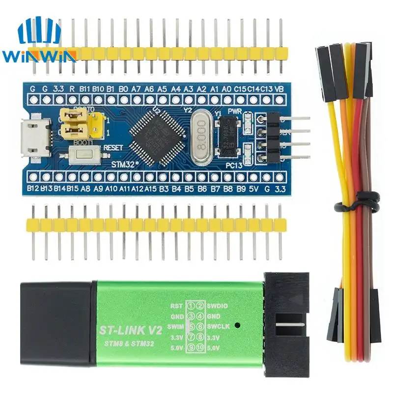
Original STM32F103C6T6 STM32F103C8T6 ARM STM32 Minimum System Development Board Module For Arduino ST-Link V2 Mini STM8
ST-Link V2 Mini STM8 Simulator Download 1. Support the full range of STM32 SWD interface debugging, simple interface (including power supply), 4 line speed, stable work; Interface definition shell directly address! Don\'t need to read instructions! 2, support all series STM8 SWIM download debugging (common development environment such as IAR, STVD etc.) are supported. Support the software version is as follows: ST - LINK Utility 2.0 and above STVD 2 and above STVP 3.2.3 and above IAR EWARM
$1.76
In Stock
Secure checkout
Fast shipping
30-day returns
Need help before you buy?
Call iBuyRobotics for product guidance, compatibility questions, bulk orders, or support.
(855) I-BUY-ROBO (855) 428-9762ST-Link V2 Mini STM8 Simulator Download
1. Support the full range of STM32 SWD interface debugging, simple interface (including power supply), 4 line speed, stable work; Interface definition shell directly address! Don\'t need to read instructions!
2, support all series STM8 SWIM download debugging (common development environment such as IAR, STVD etc.) are supported. Support the software version is as follows:
ST - LINK Utility 2.0 and above
STVD 2 and above
STVP 3.2.3 and above
IAR EWARM V6.20 and above
IAR EWSTM8 V1.30 and above
KEIL RVMDK V4.21 and above
3. Support the firmware upgrade automatically, to ensure that the ST company product support. When they leave the firmware has been upgraded to the latest V2. The J17. S4.
4. Increase the 5 v power output, the output it can protect the I/O port, not afraid of error cause damage of ST - LINK V2!
5. Easy interface to use pure copper plating 2.54 spacing horn, with 20 cm dupont line, can deal with different target board line sequence, flexible connection;
6. Use U disk aluminum alloy shell to protect the mainboard, convenient to carry, not afraid of static electricity, not afraid of tumbling.
STM32F103C8T6 ARM board
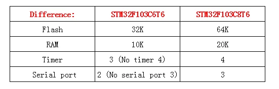
STM32F103C8T6 differs from STM32F103C6T6
This is a core chip based on for CS32F103C8T6 ARM core board, features are as follows:
1, the board based on the most basic MCU circuit, 8M and 32768 crystal circuit, USB power supply circuit.
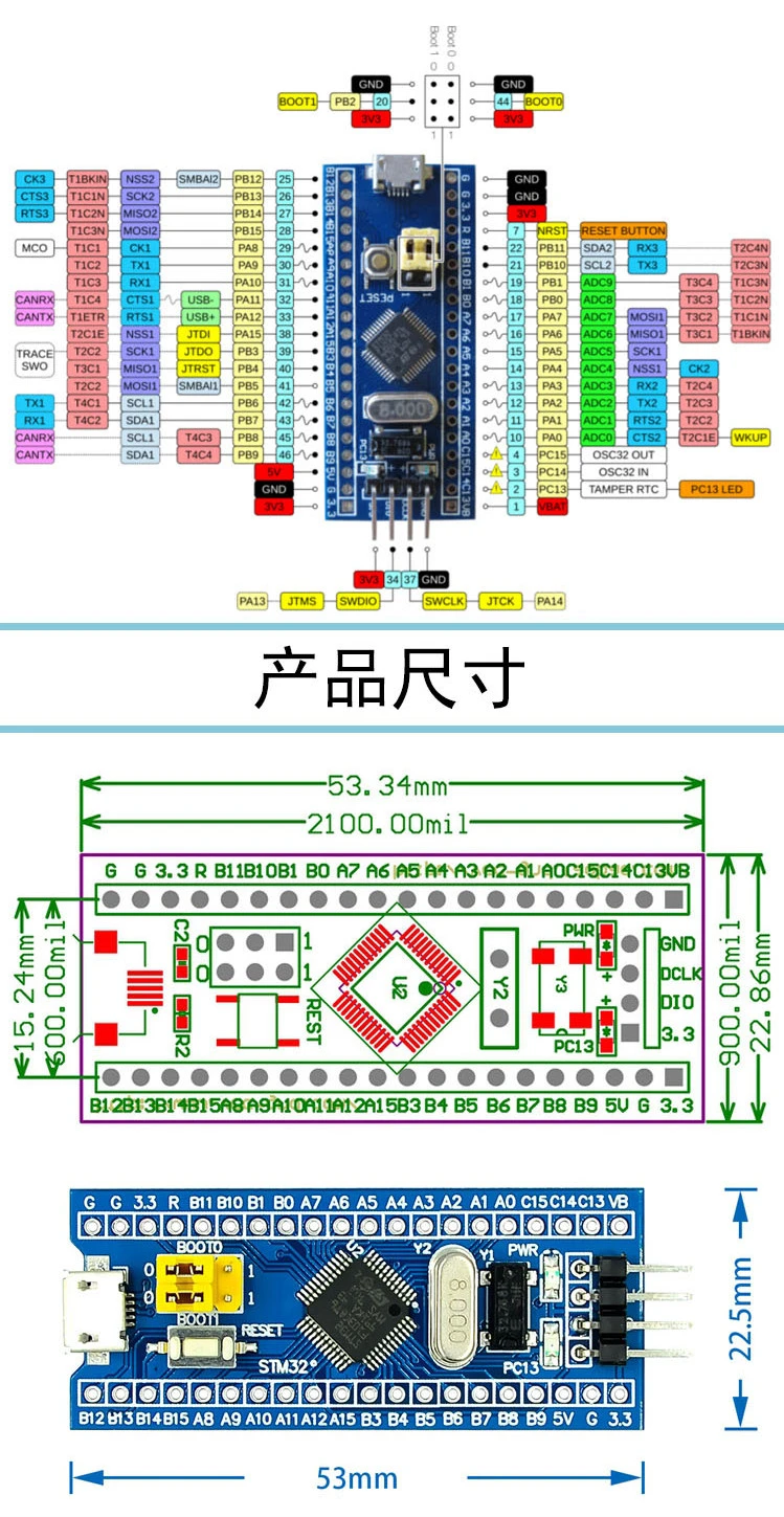
2, the core board is divided into two rows leads to all the I / O port.
3, with SWD simulation debug download interface, simple and convenient, debugging speed.
4, the use of the Mirco USB interface, you can do USB communication and power supply, USB interface, compatible with the ordinary Andrews mobile phone charger interface.
6, RTC crystal Epson brand, easy to start, more stable.
7, with double pin, but the pin does not default welding, the user according to their own application scenarios to choose their own welding direction. If welding is required, please tell the owner.
Keil can be used to compile, IAR compiler, can be downloaded through the J-Link or USART1 procedures, the procedures are the owner and debugging procedures, there are problems can consult the owner.
Chip Description:
1, 32F103C8T6
Package Type: LQFP;
Number of pins: 48;
Kernel: Cortex-M3;
Operating frequency: 72MHz;
Storage resources: 64K Byte Flash, 20KByte SRAM;
Interface Resources: 2x SPI, 3x USART, 2x I2C, 1x CAN, 37x I / O ports,
Analog-to-digital conversion: 2x ADC (12-bit / 16-channel)
Timers: 3 general timers and 1 advanced timer
Debug Download: Support JTAG / SWD debug interface to download, support for IAP.
2, RT9193: 3.3V regulator chip, the maximum output of 300mA.
Interface description:
1, SWD interface: support for simulation, download and debug.
2, Mirco USB interface: power supply and USB communication, does not support the download.
3, USART1 interface: USART1 can be used to download the program, or use the USART1 for communication.
4, MCU pin interface: leads all I / O port pins, easy to connect with peripherals.
5, 5V and 3.3V power input and output interface: commonly used in external power supply, or with other modules for common ground treatment
Other Device Description:
1, Power LED (PWR): Power indicator status, can determine whether the power supply is stable.
2, the user LED (PC13): to facilitate the I / O output test or indicate the program running.
3, start jumping choose programming mode: (1, the user flash memory 2, SRAM 3, system memory).
4, reset button: reset chip for the user program.
5, 8M Crystal: The frequency can be set to make the system clocked at 72MHz.
6,32.768KHz Crystal: Available for built-in RTC, or for calibration.
Related Products
Other products in Robots that you may find useful.
Robots
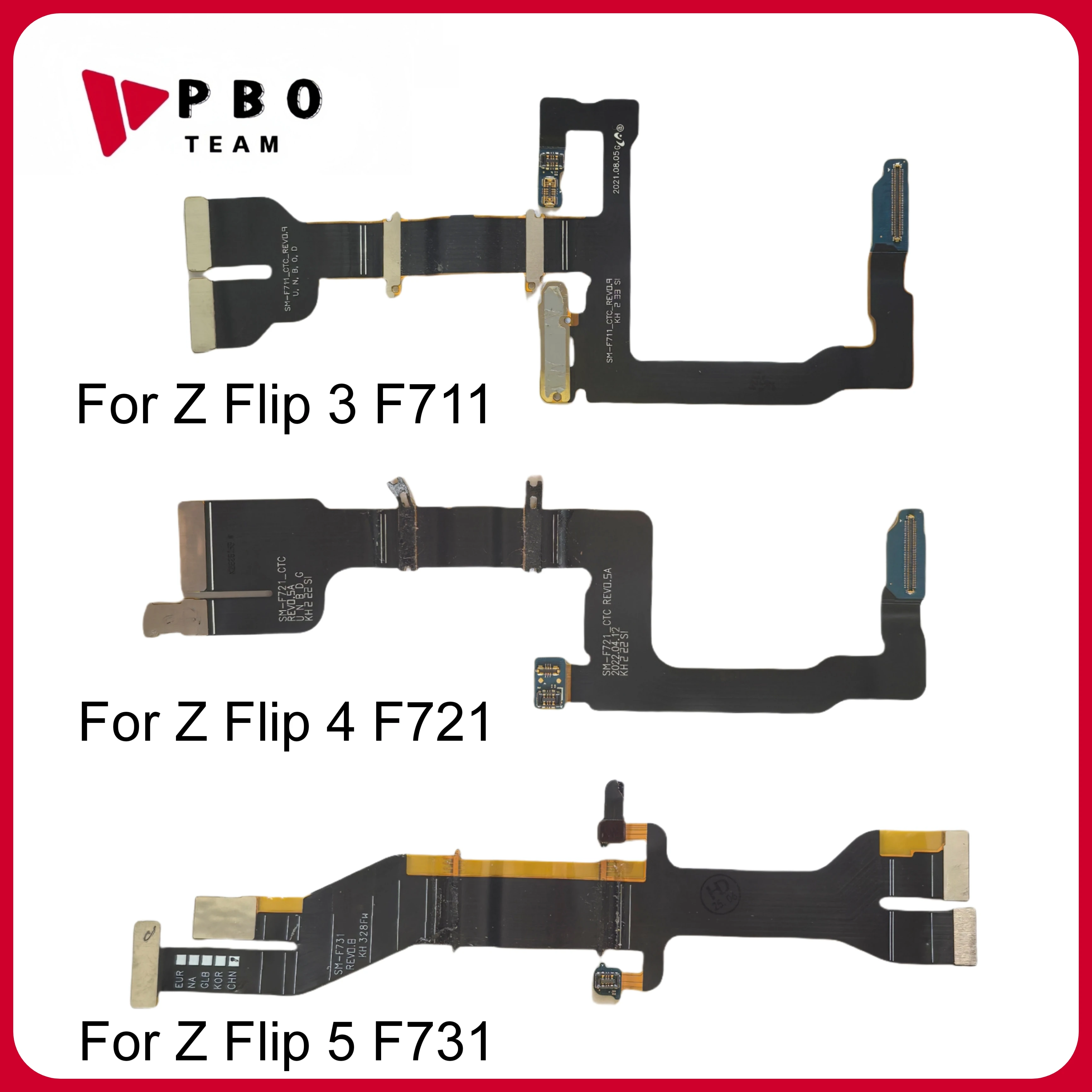
Mainboard Connector Flex Cable For Samsung Z Flip 2 3 4 5 6 F1707B F711 F721 F731 F741 LCD Display Connector Flex Cable Parts
$8.56
Robots
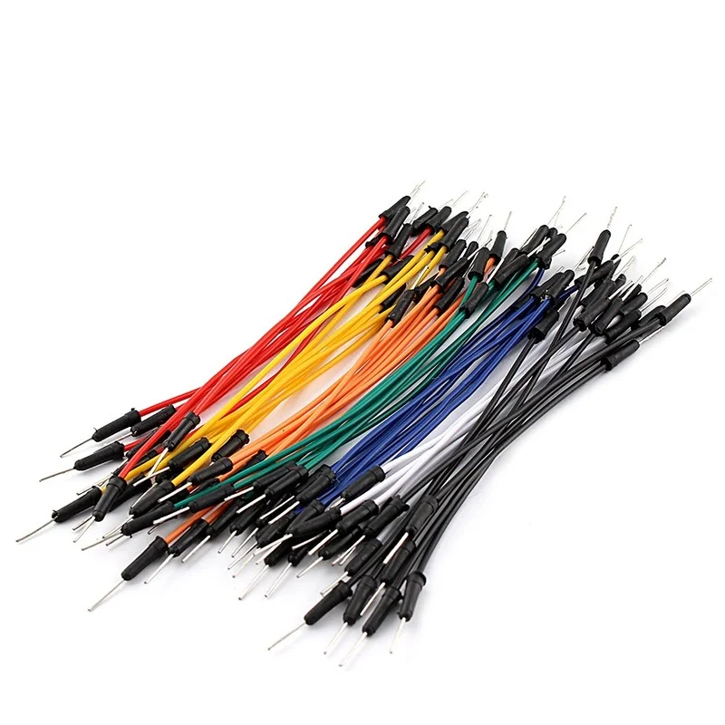
65Pcs/lot Jump Wires Cable Flexible Connect PCB Electronic Wires Breadboard Jumper Cable For Arduino Male TO Male DIY Kit
$3.44

Robots
1/2/5PCS NEW PWM Fan Splitter 1TO1/2/3/4 Adapter Cable 4pin Computer CPU Fan Splitter PC Fan Extension Power Cable E3
$5.13
Robots
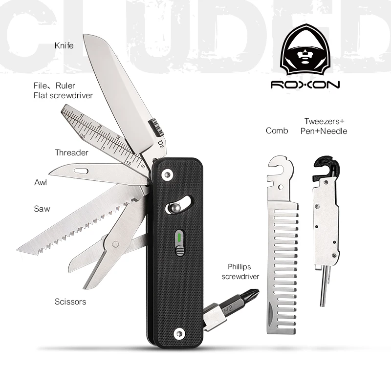
Roxon S503G Flex Companion Tool Modular Design and Customizable Pocket Tool, Preinstalled with 8 Essential Tools (1/4" Bit Drive
$39.26
Shop with confidence


